1997-2001 Honda CR250 Fork Maintenance Part 3: Assembly

0
1083

This is the Honda CR250 Fork Assembly, part 3 of the step-by-step rebuild for 1998-2001 Showa 47mm suspension forks.

You can find Part 1: Removal here, and Part 2: Inspection here.

You Can Get Parts And Tools Through Our Partner Links HERE!

Click here to open the Fork service specifications sheet in a new window.

Fork Tube Assembly

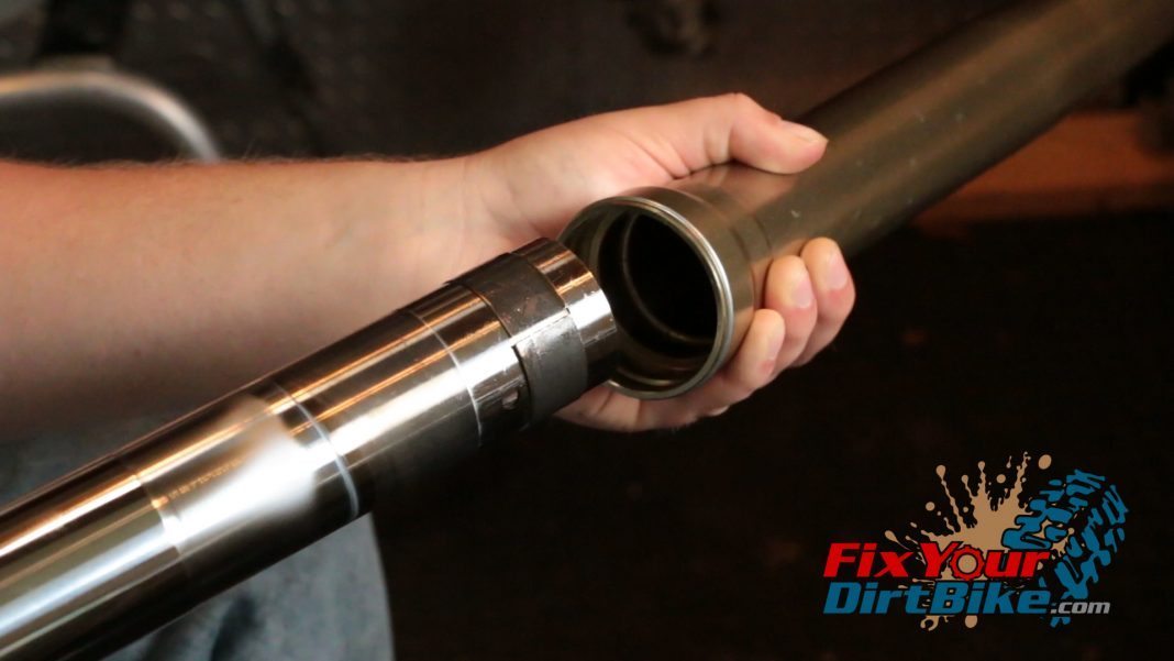
  • Step 41: Connect the fork tubes.
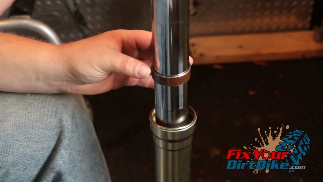
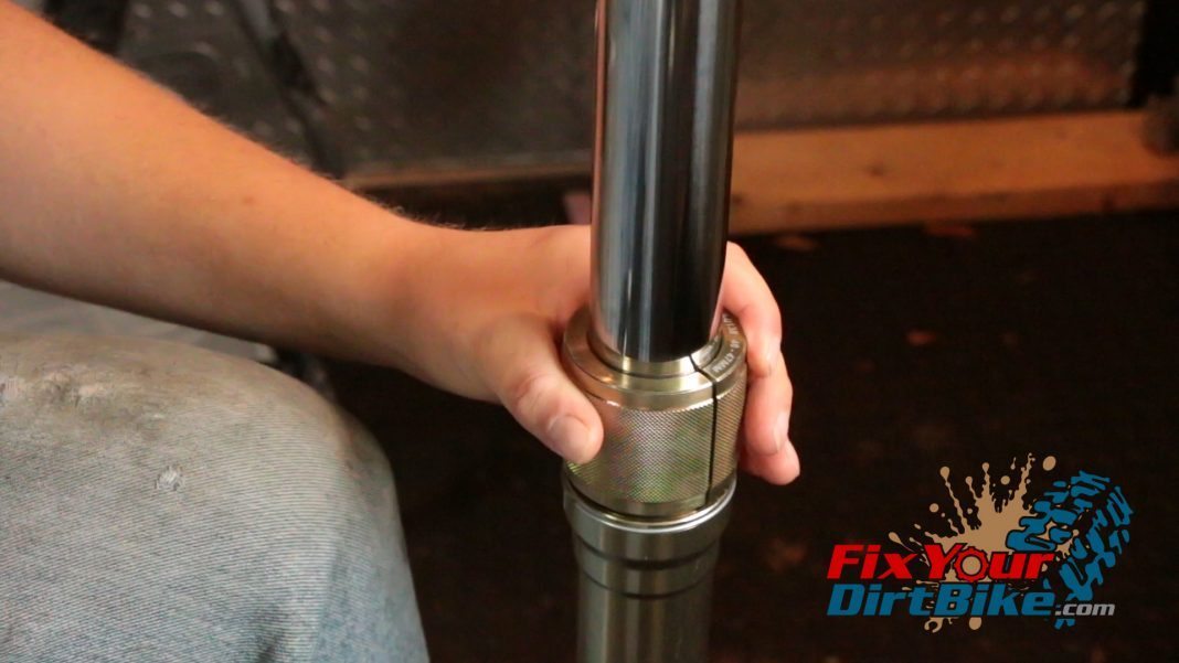
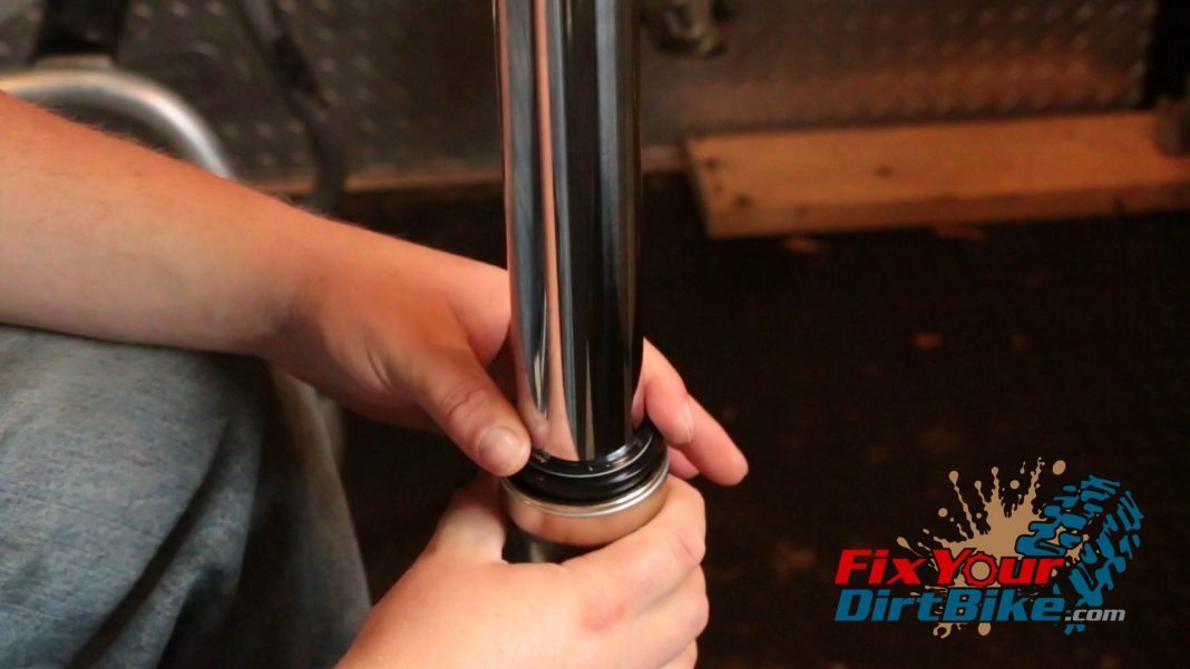
  • Step 42: Place the guide bushing.
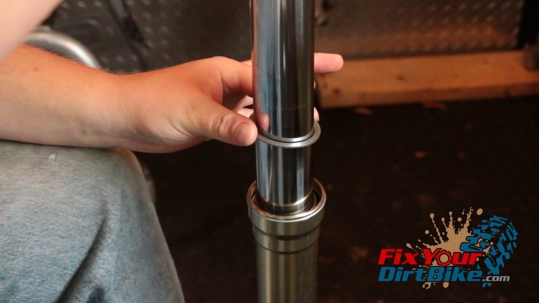
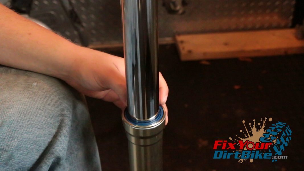
  • Step 43: Place the backup ring.
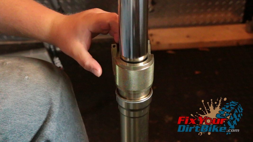
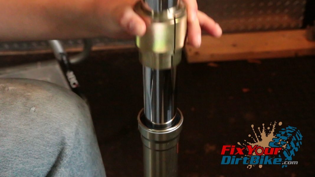
  • Step 44: Assemble the fork seal driver.
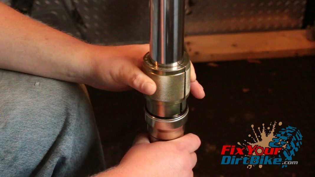
  • Step 45: Seat guide bushing.
  • Step 46: Place the oil seal.
  • Step 47: Seat the oil seal.
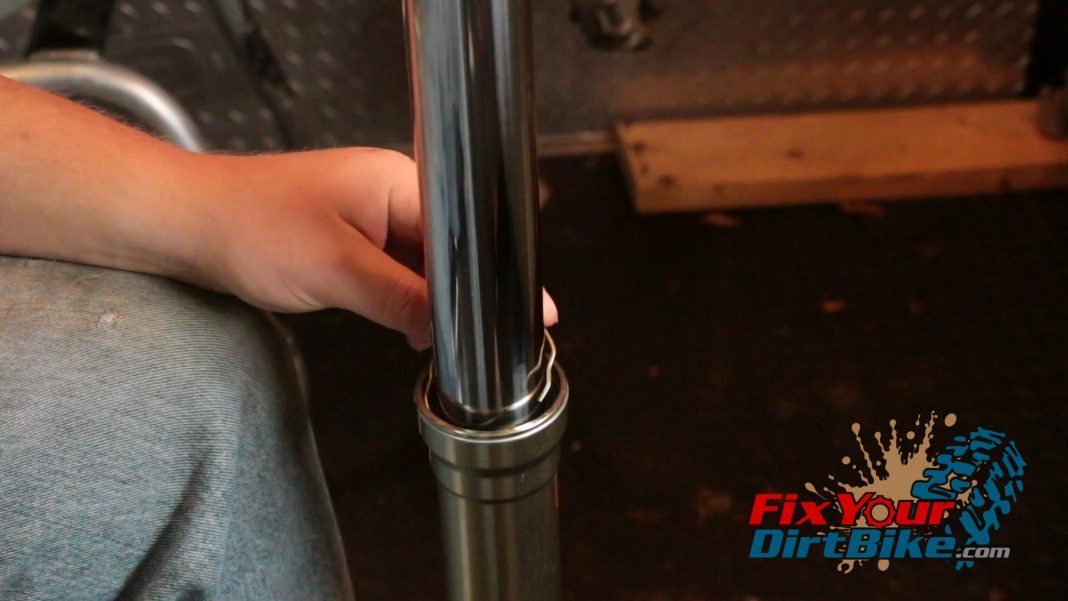
  • Step 48: Install the lock ring.
  • Step 49: Place the dust seal.
  • Step 50: Seat the dust seal.
Step 41: Connect the fork tubes.
Step 42: Place the guide bushing.
Step 43: Place the backup ring.
Step 44: Assemble fork seal driver.
Step 45: Seat guide bushing.
Step 46: Place the oil seal.
Step 46: Place oil seal.
Step 47: Seat the oil seal.
Step 48: Install the lock ring.
Step 49: Place the dust seal.
Step 50: Seat the dust seal.

Fork Oil Level

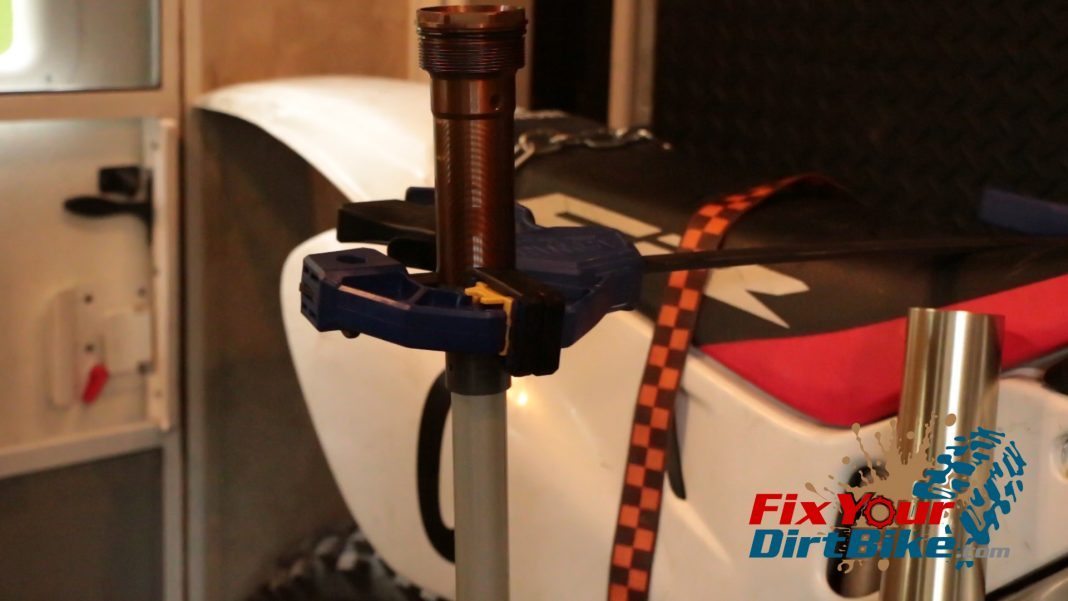
  • Step 51: Hang the compression unit in a vertical vise.
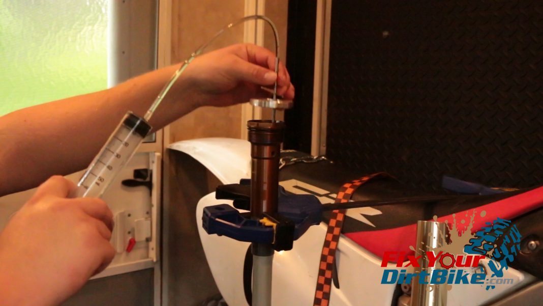
  • Step 52: Add fork oil – 180 ml.
  • Step 53: Pump piston.
  • Step 54: Set oil level – 5-10 mm.
    1. The oil level is measured from the fork cap shoulder to the top of the oil.
  • Step 55: Coat fork damper assembly with oil.
  • Step 56: Seat fork damper assembly.
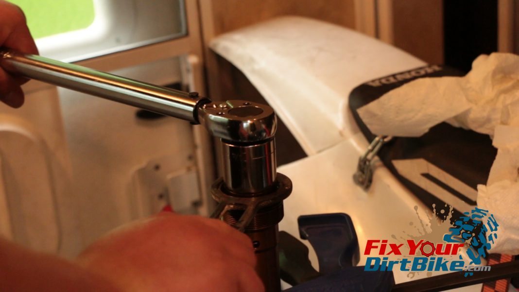
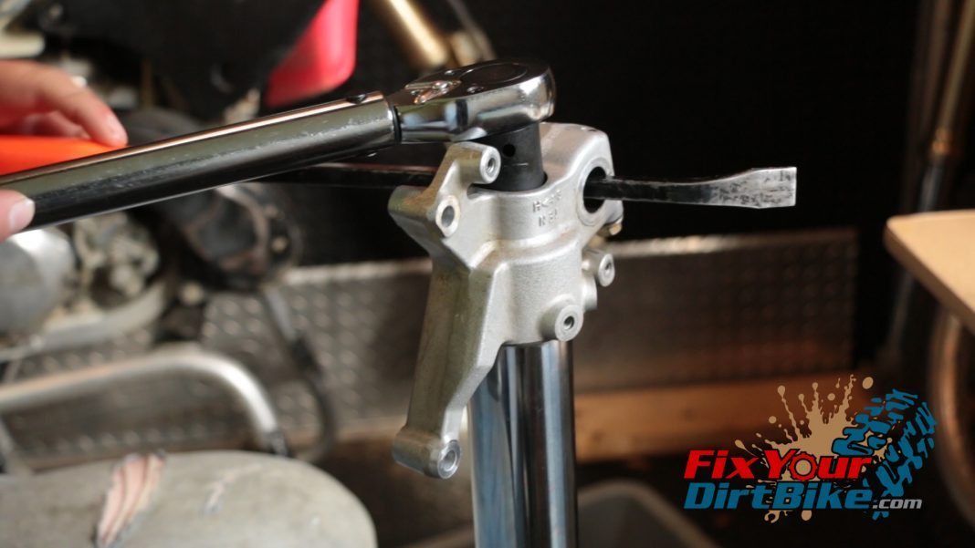
  • Step 57: Torque fork damper assembly.
    • 199787 ft-lb
      • Lock Screw (1997) – 6 inch-pounds
    • 1998-200140 ft-lb
Step 51: Hang the compression unit in a vertical vise.
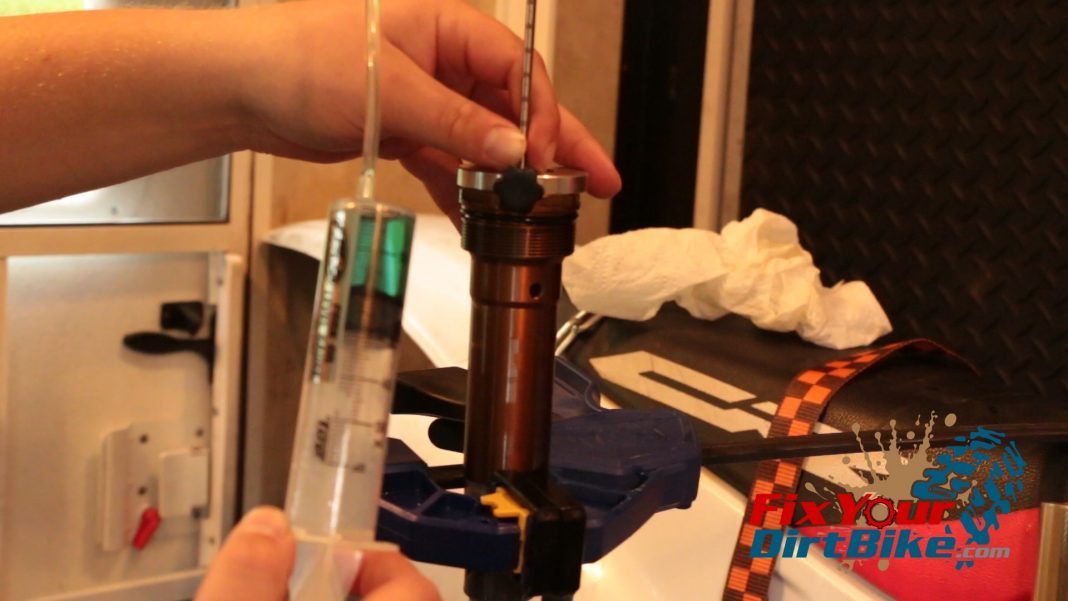
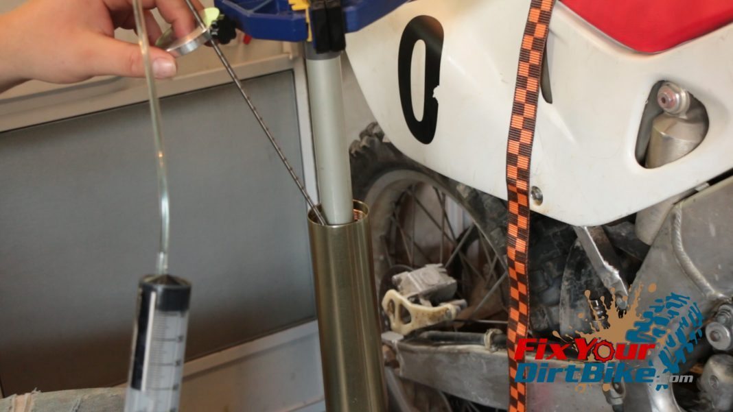
Step 52: Add fork oil - 180 ml.
Step 52: Add fork oil – 180 ml.
Step 53: Pump piston.
Step 54: Set oil level - 5-10 mm. The oil level is measured from the fork cap shoulder to the top of the oil.
Step 54: Set oil level – 5-10 mm. The oil level is measured from the fork cap shoulder to the top of the oil.
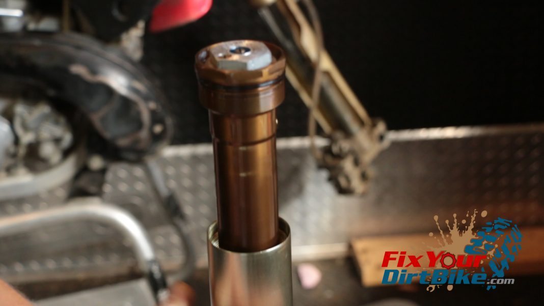
Step 55: Coat fork damper assembly with oil.
Step 56: Seat fork damper assembly.
Step 57: Torque fork damper assembly. 1997 - 87 ft-lb Lock Screw (1997) - 6 inch-pounds 1998-2001 - 40 ft-lb
Step 57: Torque fork damper assembly. 1997 – 87 ft-lb Lock Screw (1997) – 6 inch-pounds 1998-2001 – 40 ft-lb

Bleed Compression Damper

  • Step 58: Pump piston 100mm (4 in.) to void excess air.
  • Step 59: Seat lock nut.
  • Step 60: Make sure the rebound clicker is backed out all the way.
  • Step 61: Pump the rebound damper piston several times to bleed any trapped air.
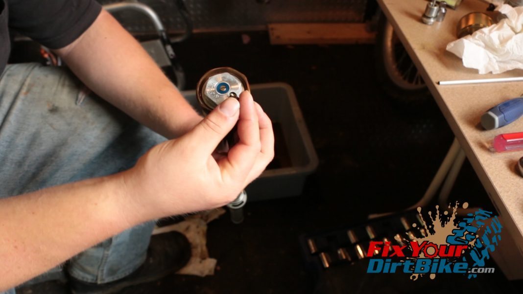
  • Step 62: Drain bled oil.
  • Step 63: Remove air bleeder screw (remember to
    put it back!
    ).
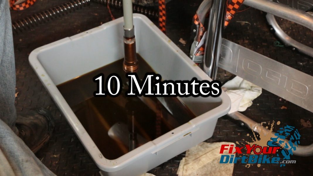
  • Step 64: Hang the compression unit upside down for 10 minutes to fully drain excess oil.
  • Step 65: Pump the piston again.
  • Step 66: Lay the compression unit flat and pump the piston in.
  • Step 67: Release piston, if the piston does not fully extend on its own, repeat the bleeding process.
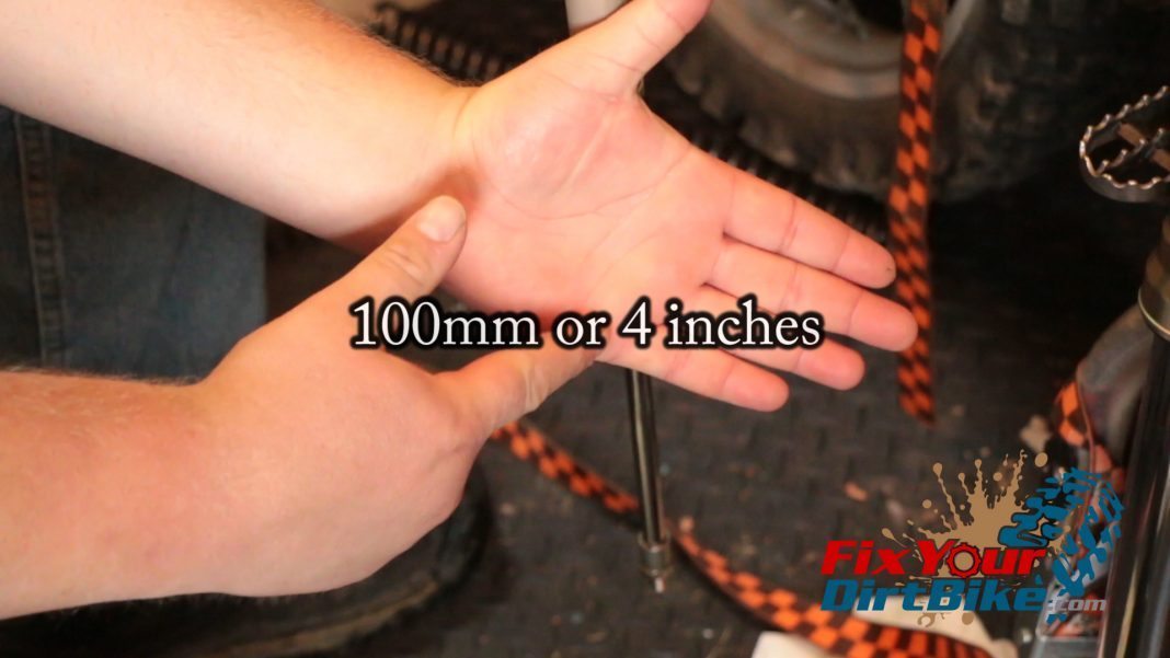
Step 58: Pump piston 100mm (4 in.) to void excess air.
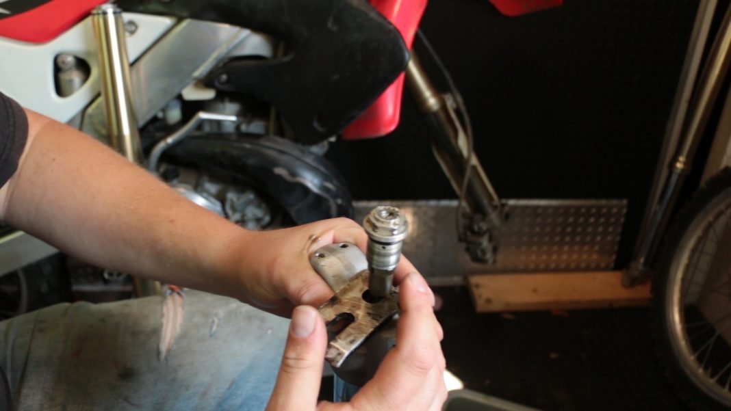
Step 59: Seat lock nut.
Step 60: Make sure the rebound clicker is backed out all the way.
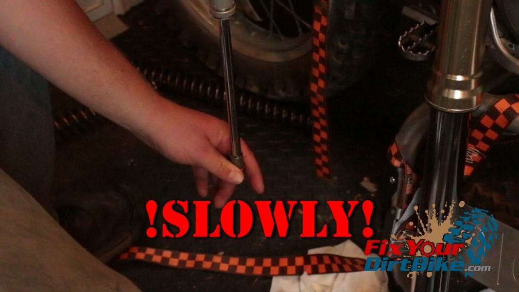
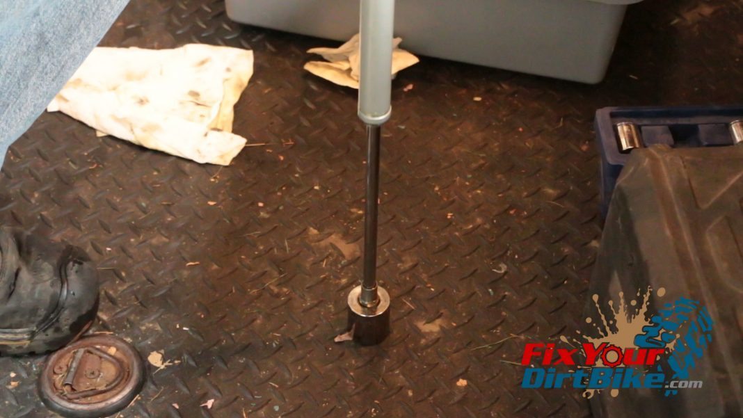
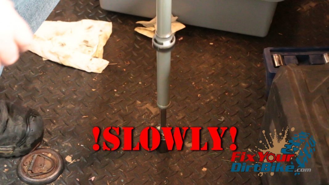
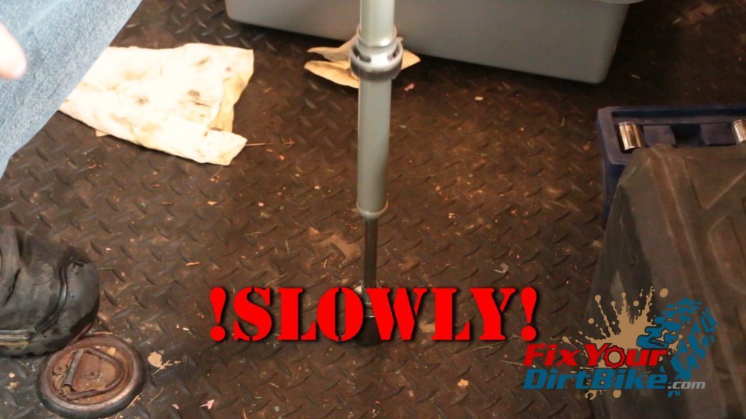
Step 61: Pump the rebound damper piston several times to bleed any trapped air.
61.1 - SLOWLY
SLOWLY
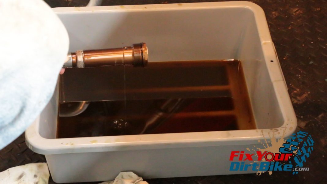
Step 62: Drain bled oil.
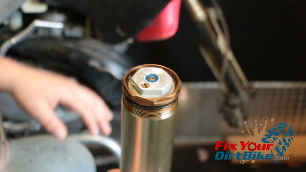
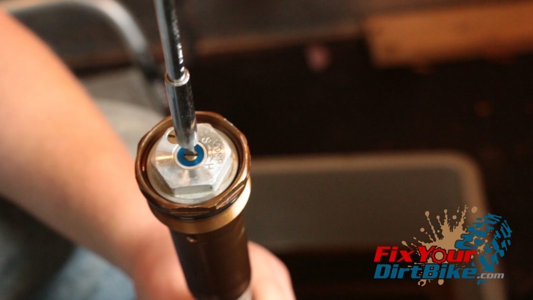
Step 63: Remove air bleeder screw (remember to put it back!).
Step 64: Hang the compression unit upside down for 10 minutes to fully drain excess oil.
Step 64: Hang compression unit upside down for 10 minutes to fully drain excess oil.
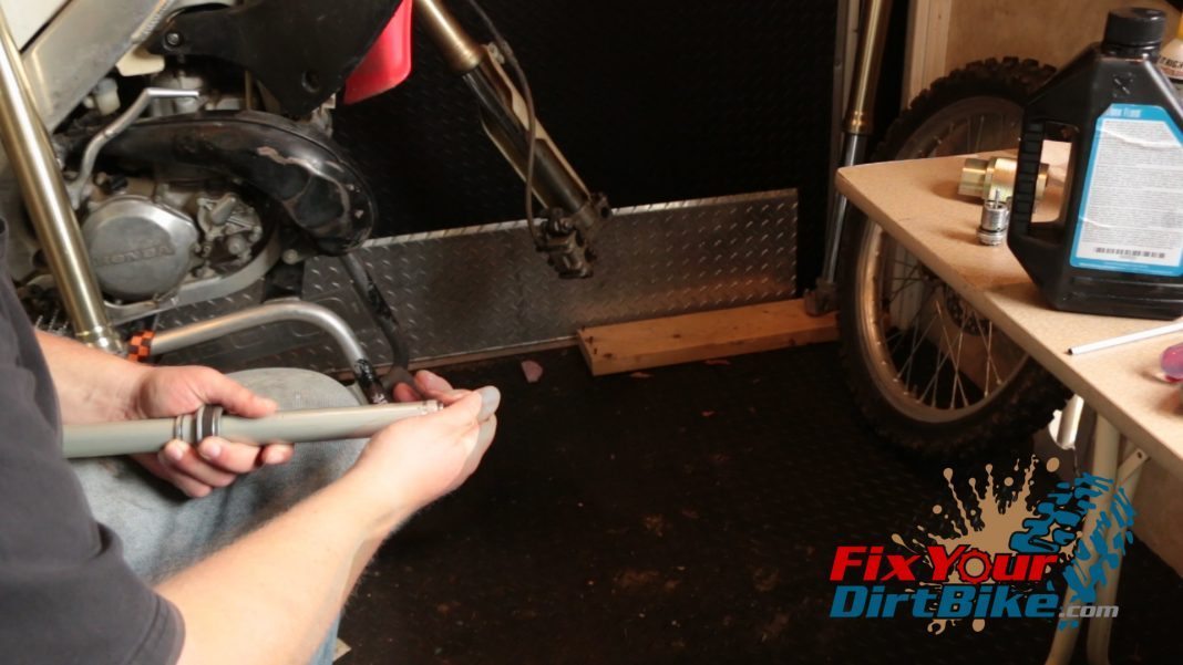
Step 65: Pump the piston again.
Step 66: Lay the compression unit flat and pump the piston in.
Step 67: Release piston, if the piston does not fully extend on its own, repeat the bleeding process.
Damper And Tube Assembly

  • Step 68: Install spring (Click here to ID your spring).
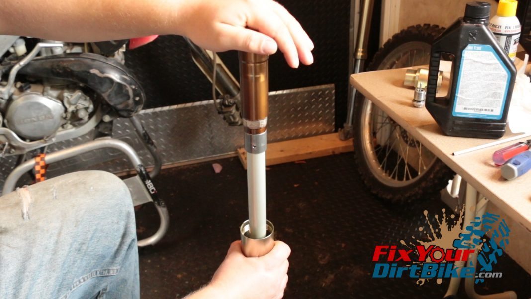
  • Step 69: Install the compression unit.
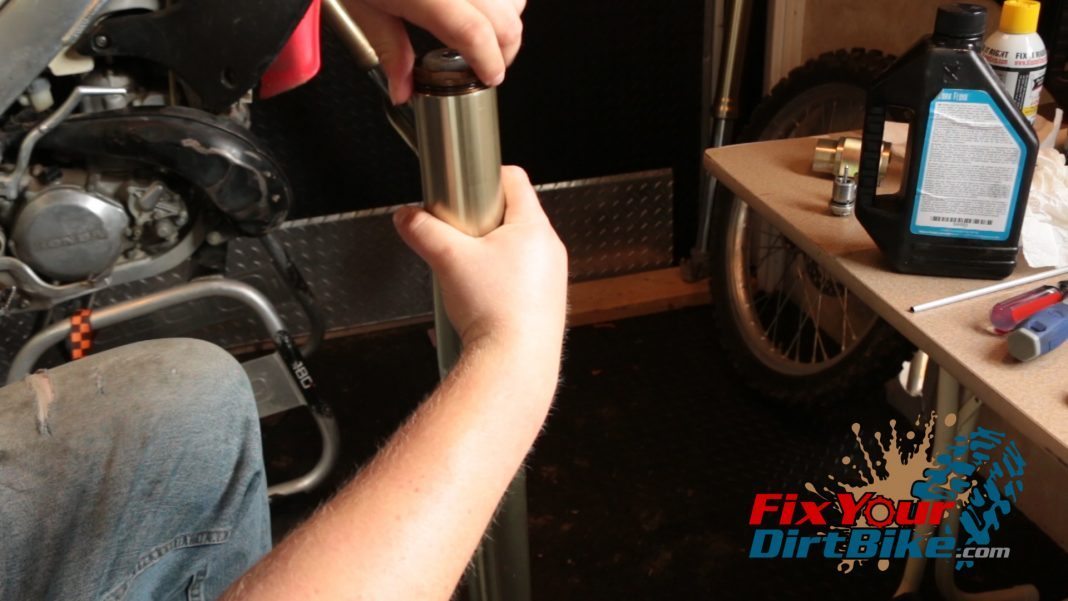
  • Step 70: Thread tube to cap.
  • Step 71: Install rod stopper.
  • Step 72: Install pushrod making sure it is lined up.
  • Step 73: Install the center bolt in the piston.
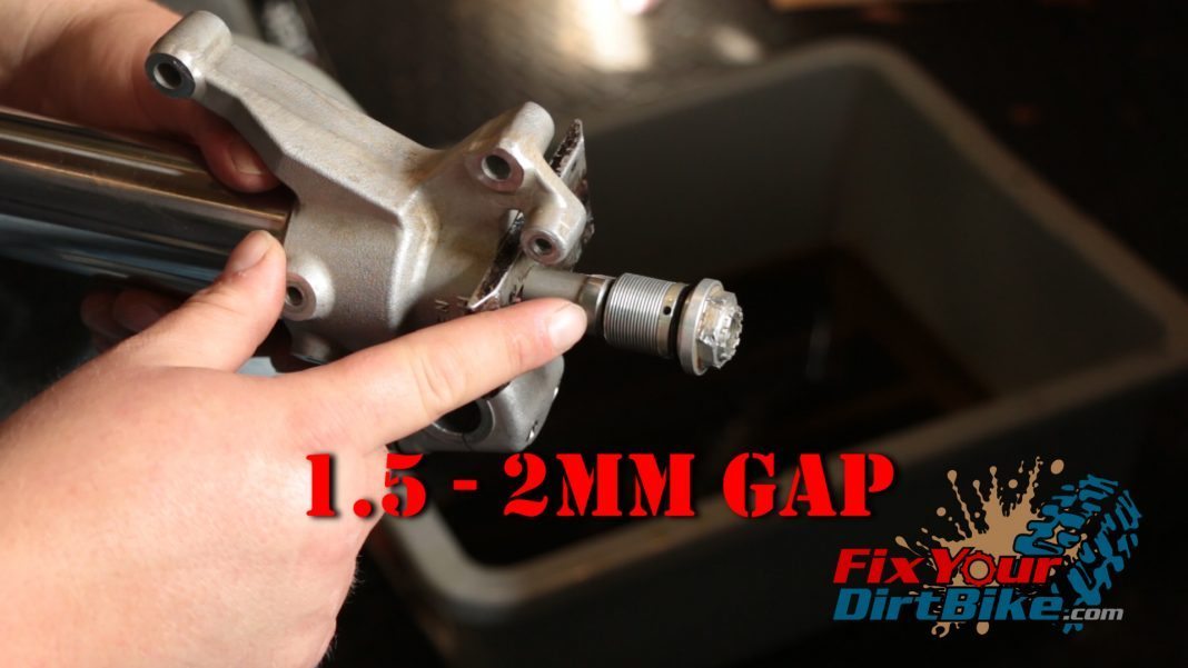
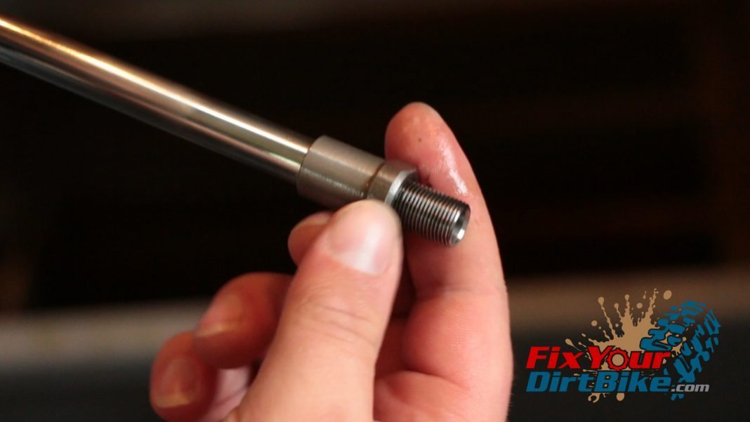
  • Step 74: Make sure the thread gap is correct – 1.5-2mm.
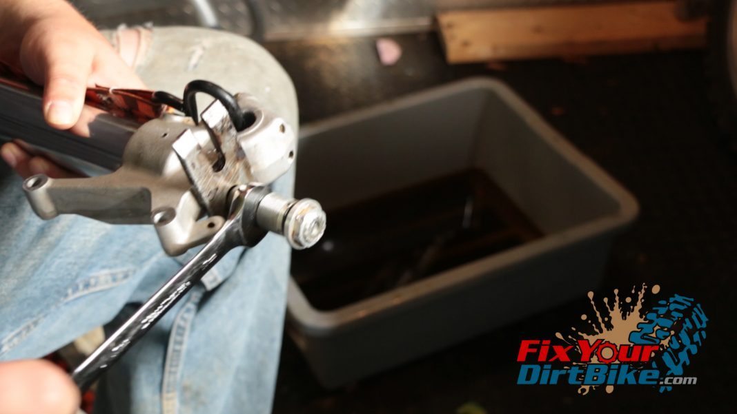
  • Step 75: Tighten lock nut to center bolt.
  • Step 76: Torque damper (compression unit)
    lock nut.

    • Lock Nut – 16 ft-lb
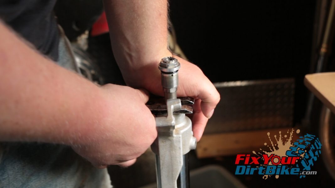
  • Step 77: Remove rod stopper.
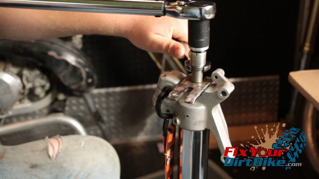
  • Step 78: Torque center bolt to the tube. – 51 ft-lb
  • Step 79: Unscrew cap again.
  • Step 80: Add oil to the tube. The spring rate determines how much oil to put into the fork tube.
  • Step 81: Reassemble the fork cap for the last time.
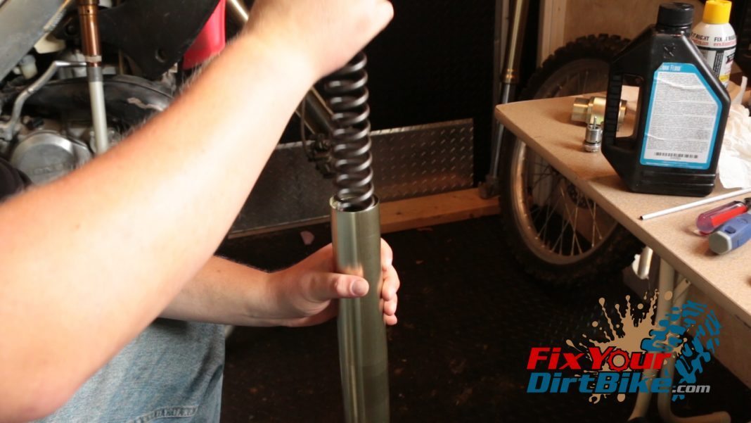
Step 68: Install spring (Click here to ID your spring).
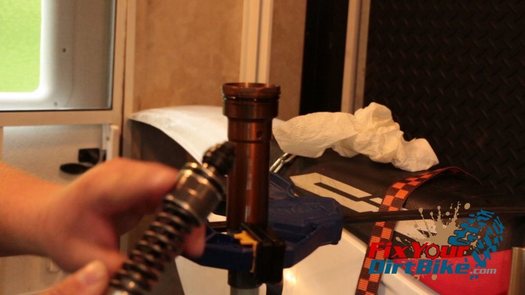
Step 69: Install the compression unit.
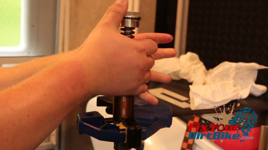
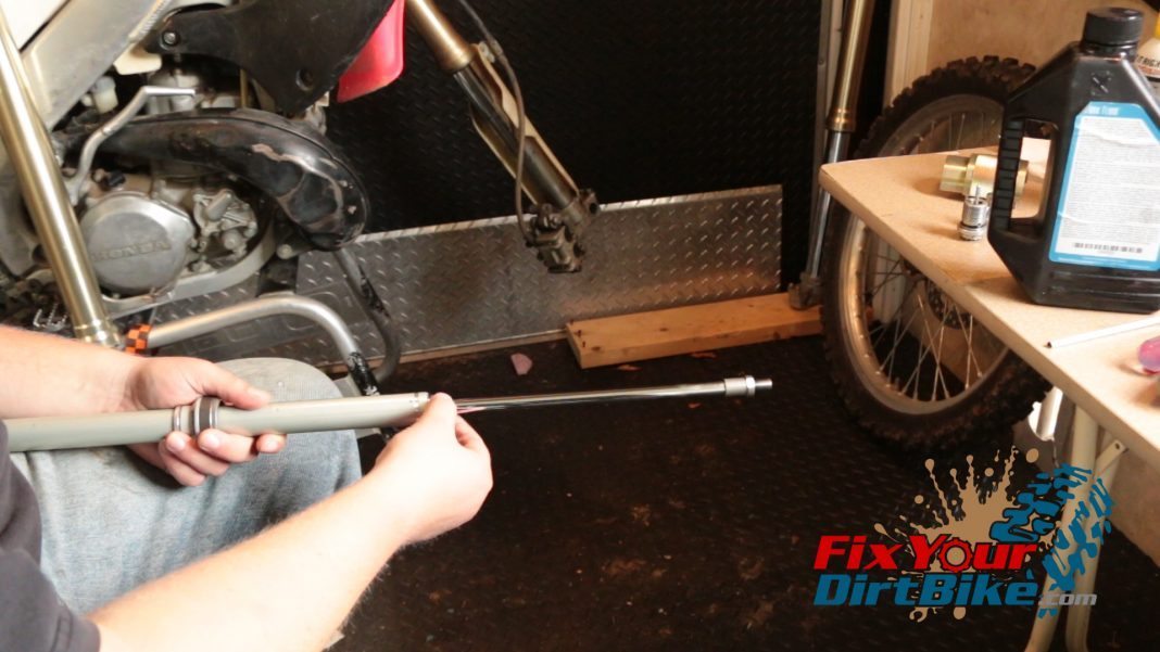
Step 70: Thread tube to cap.
Step 71: Install rod stopper.
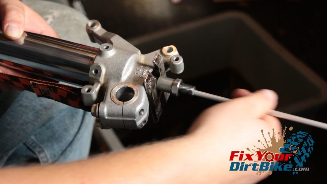
Step 72: Install pushrod making sure it is lined up.
Step 73: Install the center bolt in the piston.
Step 74: Make sure the thread gap is correct - 1.5-2mm.
Step 74: Make sure the thread gap is correct – 1.5-2mm.
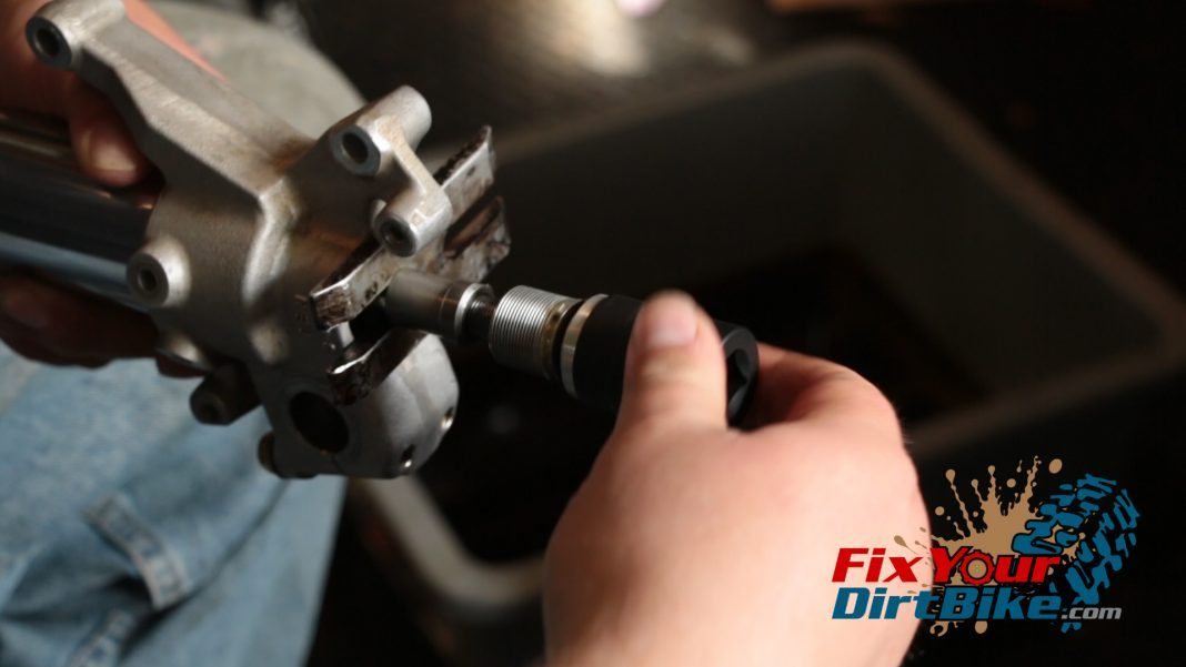
Step 75: Tighten lock nut to center bolt.
Step 76: Torque damper (compression unit) lock nut. Lock Nut - 16 ft-lb
Step 76: Torque damper (compression unit) lock nut. Lock Nut – 16 ft-lb
Step 77: Remove rod stopper.
Step 78: Torque center bolt to the tube. - 51 ft-lb
Step 78: Torque center bolt to the tube. – 51 ft-lb
Step 79: Unscrew cap again.
Step 80: Add oil to the tube. The spring rate determines how much oil to put into the fork tube.
Step 81: Reassemble the fork cap for the last time.
Fork Installation

  • Step 82: Install your fork on the triple clamp.
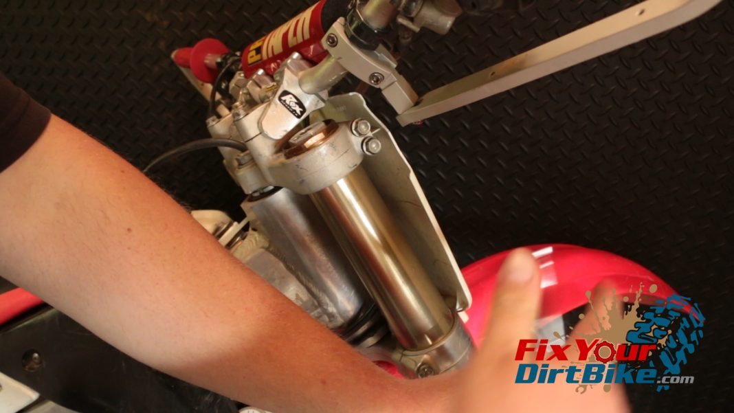
  • Step 83: Torque lower bridge bolts only – 15 ft-lb.
  • Step 84: Torque fork cap.
    • 1997 – 40 ft-lb
    • 1998-2001 – 22 ft-lb
    • (Torque upper bridge bolts – 16 ft-lb)
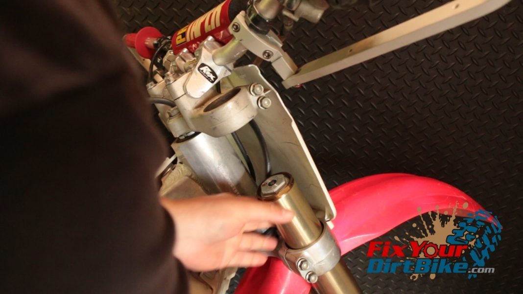
Step 82: Install your fork on the triple clamp.
Step 83: Torque lower bridge bolts only - 15 ft-lb.
Step 83: Torque lower bridge bolts only – 15 ft-lb.
Step 84: Torque fork cap. 1997 - 40 ft-lb 1998-2001 - 22 ft-lb (Torque upper bridge bolts - 16 ft-lb)
Step 84: Torque fork cap. 1997 – 40 ft-lb – 1998-2001 – 22 ft-lb (Torque upper bridge bolts – 16 ft-lb)
If you have any questions or anything to add, please leave them in the comments or on our FaceBook page!

Keep Your ’97-’01 CR250 Running Right!

Large-Final

This site uses Akismet to reduce spam. Learn how your comment data is processed.