1997-2001 Honda CR250 Clutch Maintenance Part 3: Installation

0
281

This is the 1997-2001 Honda CR250 Clutch Install, Part 3 of the step-by-step clutch maintenance series. You can find Part 1: Removal and Part 2: Inspection.

You Can Get Parts And Tools Through Our Partner Link → https://amzn.to/4h4lDKq

You must reference the Service & Torque Specs table for the installation process.

1997-2001 Honda CR250 Clutch Install

Click here to open the service limits and torque specification chart in a new window.

  • Step 33: Install the clutch lifer lever.
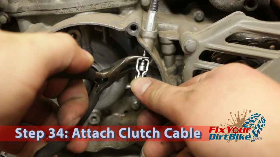
  • Step 34: Connect the clutch cable.
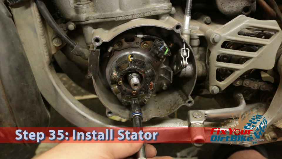
  • Step 35: Install the stator.
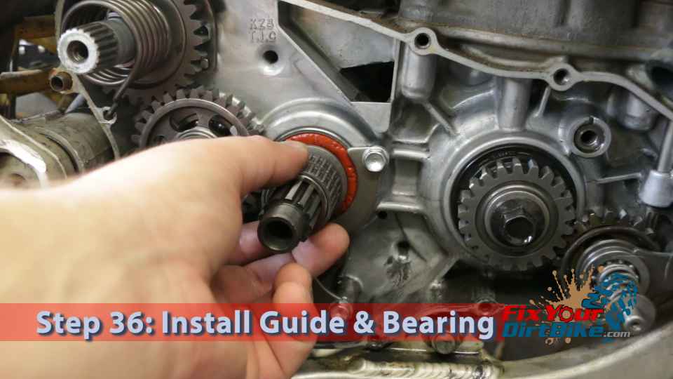
  • Step 36: Install the clutch outer guide and needle bearing.
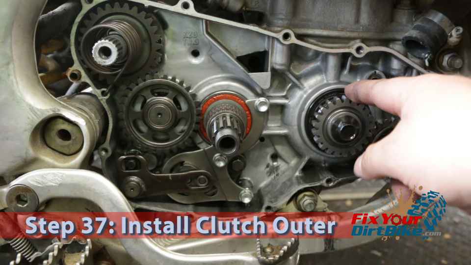
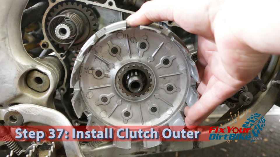
  • Step 37: Install the clutch outer basket.
    • You will need to align the clutch inner gear teeth with the idle gear and the outer teeth with the primary drive gear.
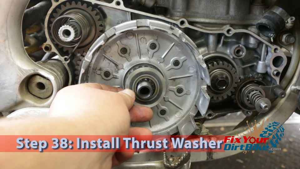
  • Step 38: Install the inner thrust washer.
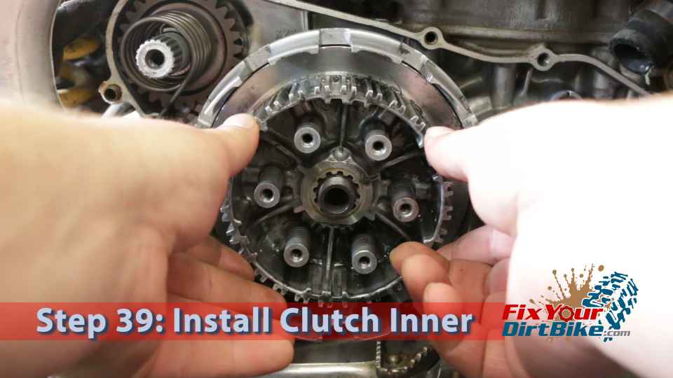
  • Step 39: Install the clutch inner.
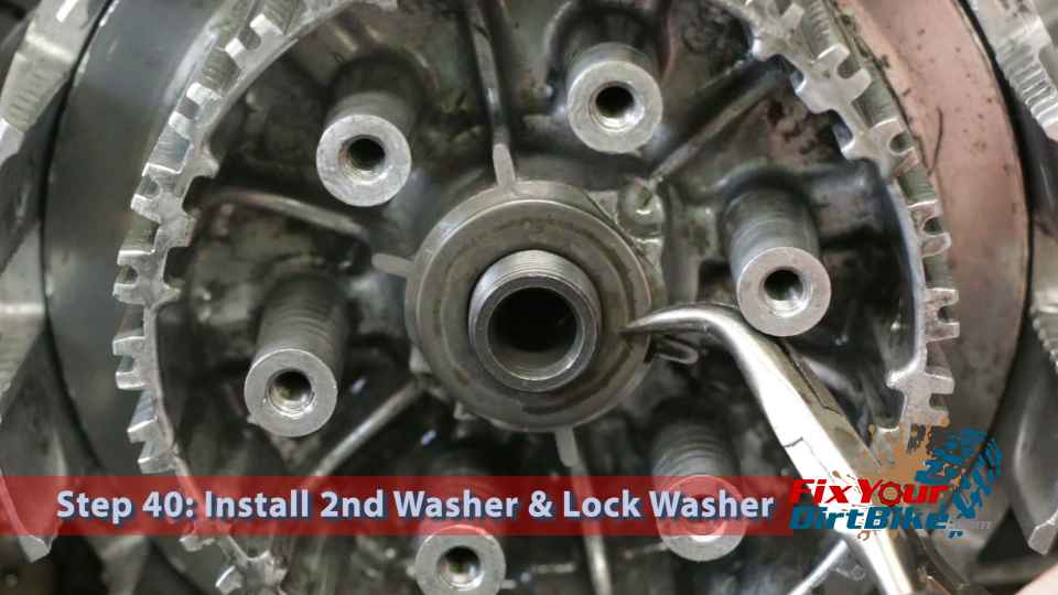
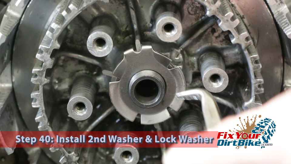
  • Step 40: Install the outer thrust washer and lock washer.
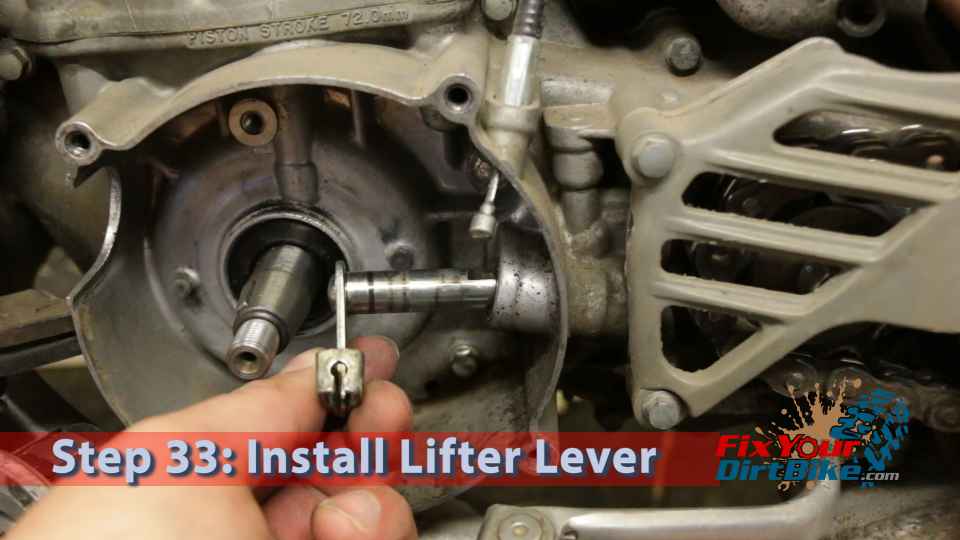
Step 33: Install the clutch lifer lever.
Step 34: Connect the clutch cable.
Step 35: Install the stator.
Step 36: Install the clutch outer guide and needle bearing.
Step 37: Install the clutch outer basket.

Step 37.1: Install Clutch Outer

Step 38: Install the inner thrust washer.
Step 39: Install the clutch inner.
Step 40: Install the outer thrust washer and lock washer.
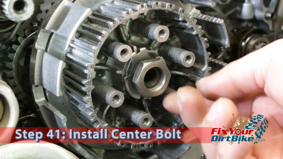
  • Step 41: Install the center bolt.
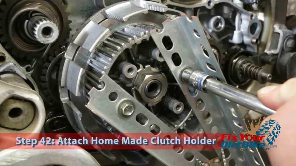
  • Step 42: Bolt the clutch holder tool to the inner using the spring bolts.
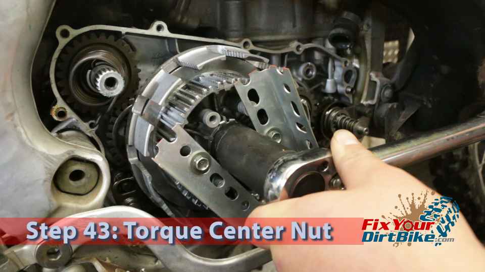
  • Step 43: Torque the center nut (59 ft.lb) and remove the holder tool.
  • Step 44: Fold the small edge of the lock washer up against the side of the center nut, making the tab as flat as possible.
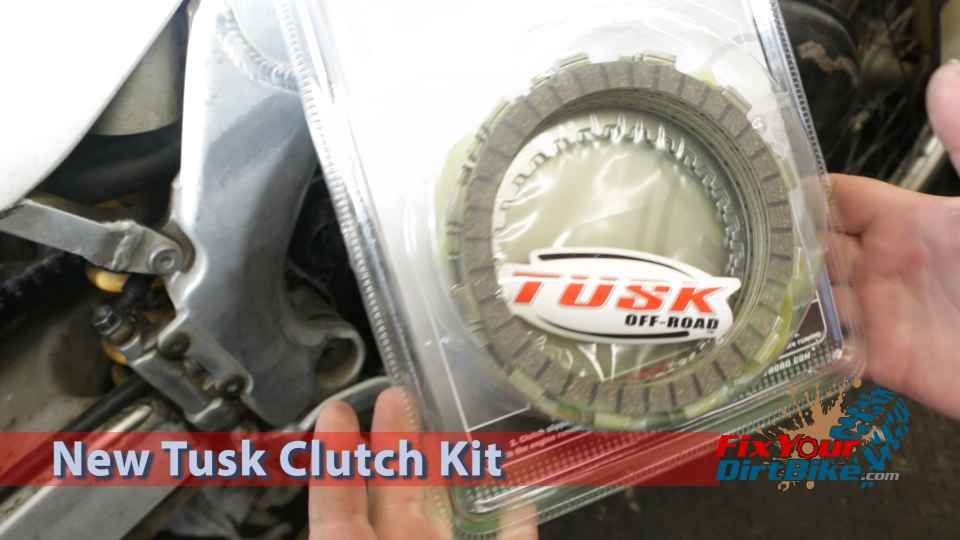
  • New Clutch: The clutch discs and springs in this 1997 Honda CR250 were out of spec, so we will install a new Tusk heavy-duty kit.
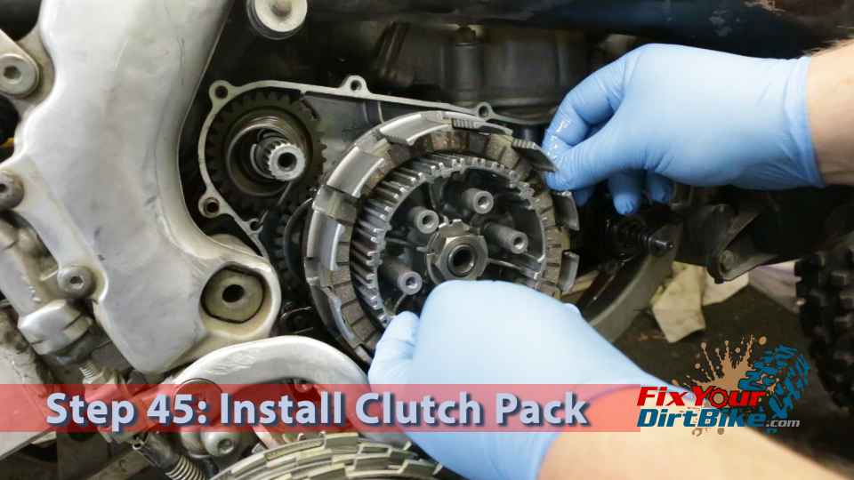
  • Step 45: Install the clutch plates and friction discs.
    • The friction discs and clutch plates will alternate, starting with a friction disc.
    • Coat both sides of each disc and plate as you install them.
Step 40.1: Install 2nd Washer & Lock Washer

Step 41: Install the center bolt.
Step 42: Bolt the clutch holder tool to the inner using the spring bolts.
Step 43: Torque the center nut (59 ft.lb) and remove the holder tool.
Step 44: Fold the small edge of the lock washer up against the side of the center nut.  Get the tab as flat as possible.
Step 44: Fold the small edge of the lock washer up against the side of the center nut, making the tab as flat as possible.
New Clutch: The clutch discs and springs in this 1997 Honda CR250 were out of spec so we will be installing a new Tusk heavy duty kit.
New Clutch: The clutch discs and springs in this 1997 Honda CR250 were out of spec, so we will install a new Tusk heavy-duty kit.
Step 45: Install the clutch plates and friction discs.
  • Step 46: Install the lifter and lifter rod.
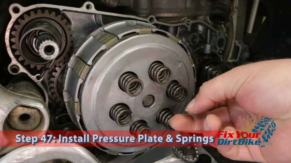
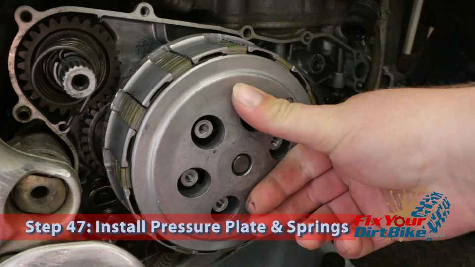
  • Step 47: Install the pressure plate and springs.
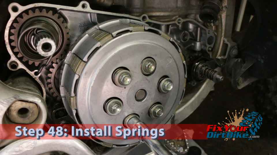
  • Step 48: Tighten the clutch spring bolts in a crossing pattern to ensure even pressure.
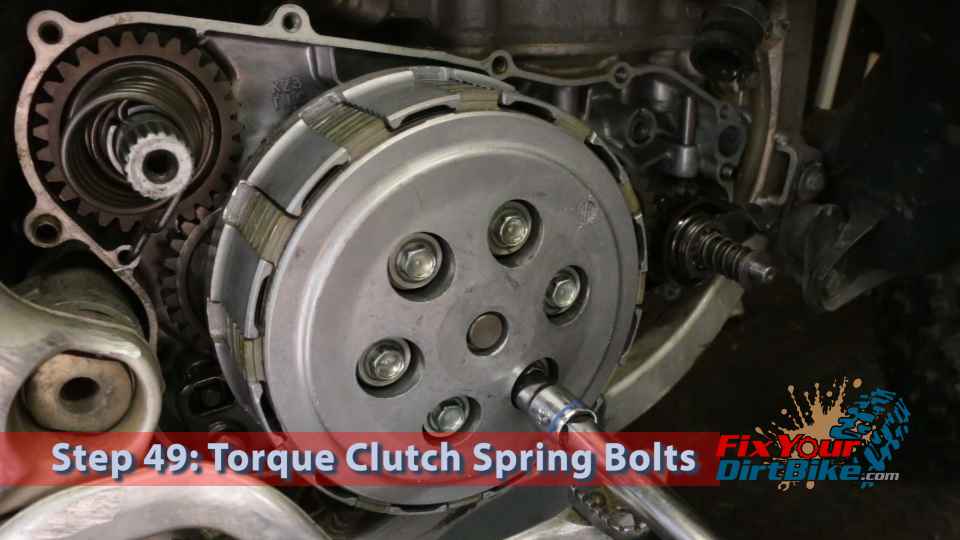
  • Step 49: Torque the clutch spring bolts (88 in.lb) using the same crossing pattern.
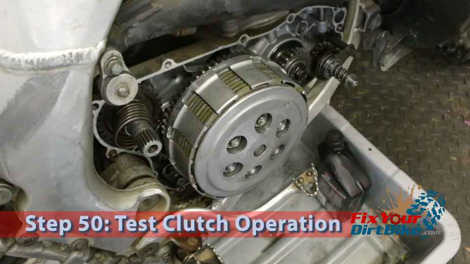
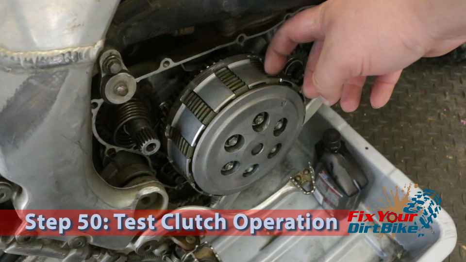
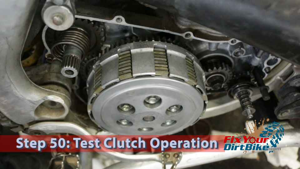
  • Step 50: Test the clutch lifter and spring operation.
    • Pull the clutch lever to ensure the lifter lever is connected to the rod.
    • Push the friction plates back and forth with the clutch engaged to check for smooth operation.
    • Place the bike in 1st gear, then manually rotate the rear tire while operating the clutch in and out. The clutch will not work as expected because the plates are not broken. The purpose of this test is to make sure everything is rotating correctly.
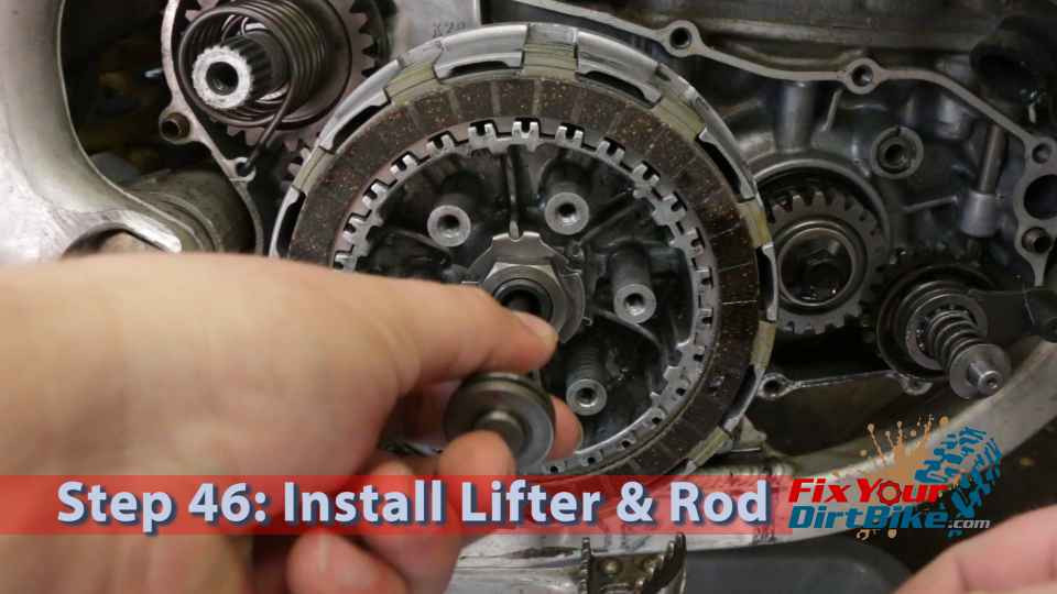
Step 46: Install the lifter and lifter rod.
Step 47: Install the pressure plate and springs.

Step 47.1: Install Pressure Plate & Springs

Step 48: Tighten the clutch spring bolts in a crossing pattern to ensure even pressure.

*INCH pounds

49: Torque the clutch spring bolts (88 in.lb) using the same crossing pattern.
Pull the clutch lever to make sure the lifter lever is connected to the rod.
Pull the clutch lever to ensure the lifter lever is connected to the rod.
With the clutch engaged, push the friction plates back and forth to check for smooth operation.
Push the friction plates back and forth with the clutch engaged to check for smooth operation.
Place the bike in 1st gear then manually rotate the rear tire with operating the clutch in and out. The clutch will not work as you would expect because the plates are not broken in. The purpose of this test is to make sure everything is rotating correctly.
Place the bike in 1st gear, then manually rotate the rear tire while operating the clutch in and out. The clutch will not work as expected because the plates are not broken. The purpose of this test is to make sure everything is rotating correctly.
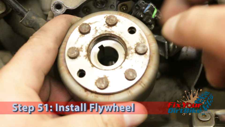
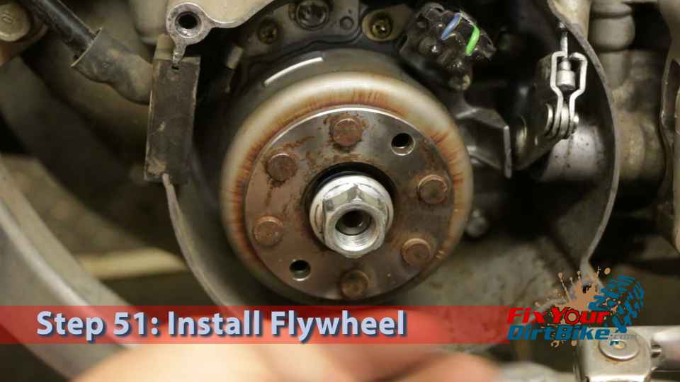
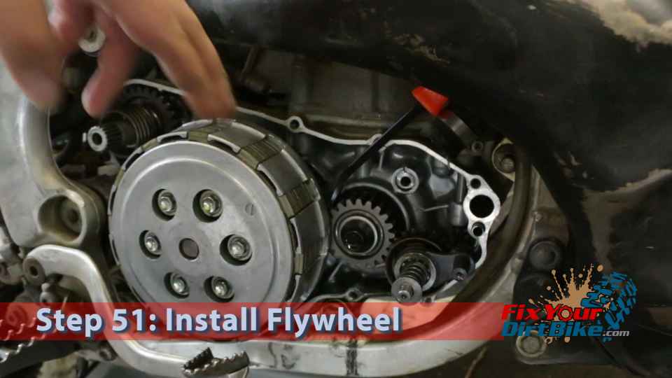
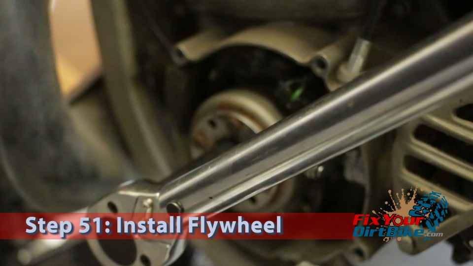
  • Step 51: Install the flywheel.
    • Ensure the notch in the flywheel is lined up with the woodruff key.
    • Install the washer and nut.
    • Jam the primary drive gear with a wide flat screwdriver to keep the crankshaft from turning.
    • Torque the flywheel bolt (40 ft.lb).
    • Install the flywheel cover.
    • NOTE: Be extremely careful when jamming the primary drive gear. Make sure the screwdriver is flat on the teeth. If you have a flywheel holder, use it!
  • Step 52: Install a new crank cover gasket.
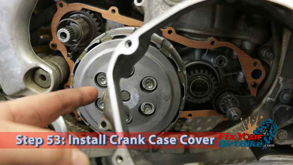
  • Step 53: Install the crankcase cover.
    • The tab on the rear of the cover needs to clear the frame, so you will need to install the rear of the cover first.
    • Be careful as you install the cover; the Kickstarter spring may pop out of the crankcase.
    • Rotate the water pump fins so the gear lines up with the primary drive gear.
    • Tap the case with a hammer if you need to.
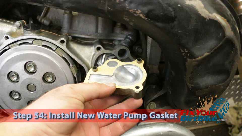
  • Step 54: Install new gaskets on the water pump cover.
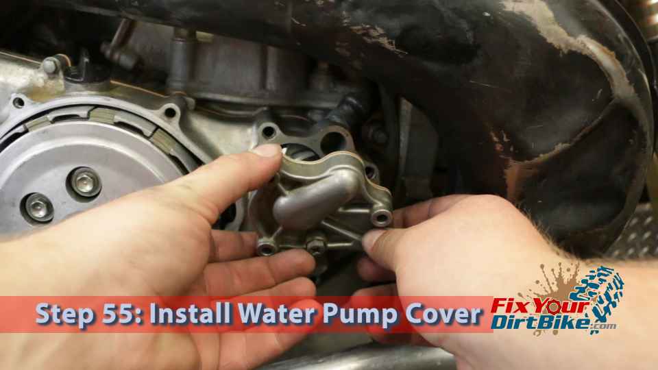
  • Step 55: Install the water pump cover.
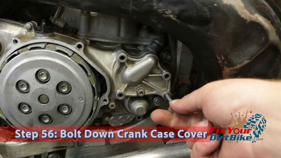
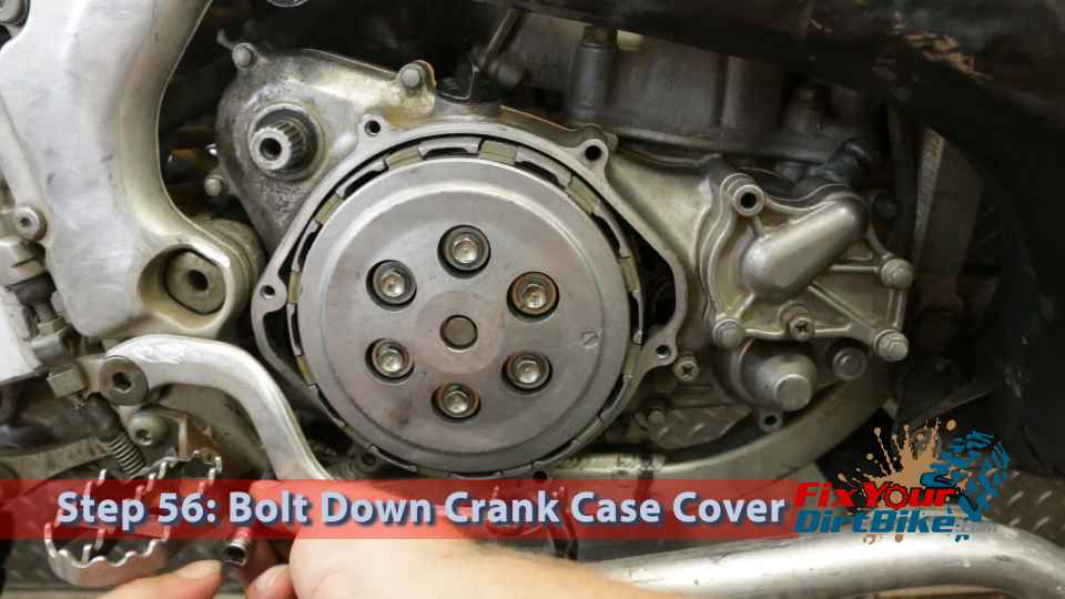
  • Step 56: Bolt down the crankcase cover.
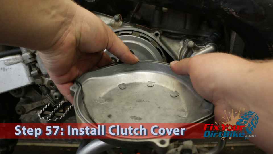
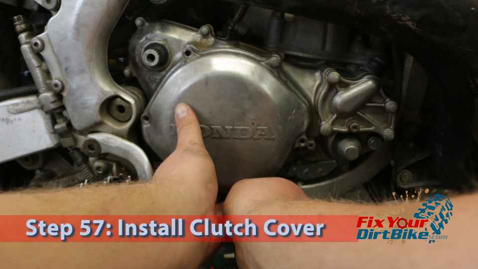
  • Step 57: Install a new O-ring and install the clutch cover.
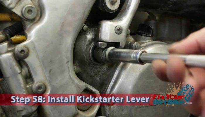
  • Step 58: Install the kickstarter lever.
  • Step 59: Torque the kickstarter lever bolt.
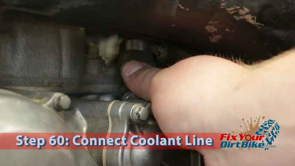
  • Step 60: Connect the coolant line.
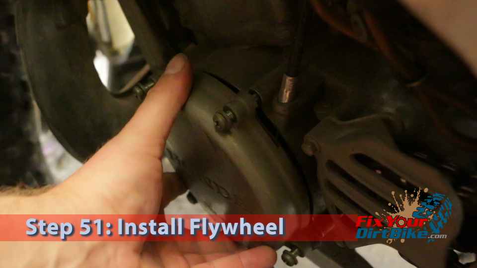
Make sure the notch in the flywheel is lined up with the woodruff key.
Ensure the notch in the flywheel is lined up with the woodruff key.
Install the washer and nut
Install the washer and nut.
Jam the primary drive gear with a wide flat screwdriver to keep the crankshaft from turning.
Torque the flywheel bolt (40 ft.lb).
Install the flywheel cover.
Step 52: Install a new crank cover gasket.
Step 53: Install the crankcase cover.
Step 54: Install new gaskets on the water pump cover.
Step 55: Install the water pump cover.

This is where knowing what bolt goes where comes in very handy!

Step 56: Bolt down the crankcase cover.
This is where knowing what bolt goes where comes in very handy!
Step 57: Install a new O-ring and install the clutch cover.

Step 57.1: Install Clutch Cover

Step 58: Install the kickstarter lever.
Step 59: Torque the kickstarter lever bolt.
Step 60: Connect the coolant line.
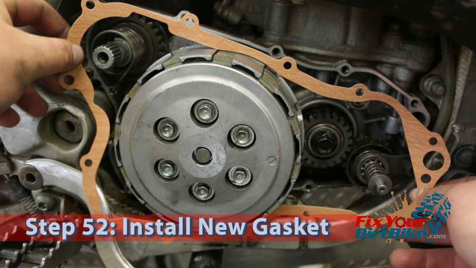
Remember to refill the Coolant and Oil!

If you have any questions or comments, please leave them in the comments or on our Facebook page!

Keep Your ’97-’01 CR250 Running Right!
Fix Your Dirt Bike Logo

This site uses Akismet to reduce spam. Learn how your comment data is processed.