1997-2001 Honda CR250 – Top End Service – Part 10: Exhaust Valve Installation

0
345
1997 - 2001 Honda CR250 - Top End Service - Part 10 - Exhaust Valve Installation

How To Install The Exhaust Valve On Your 97-01 Honda CR250
1997 - 2001 Honda CR250 - Top End Service - Part 10 - Exhaust Valve InstallationThe Tools You Will Need

The Parts You Will Need

  • Left Valve Cap O-ring – Part Number: 91302-001-020

Pre-Service Notes

  • I recommend opening the Service & Torque Specs in a new tab for easy reference.
  • If you need parts and tools, make sure to buy them here! → https://amzn.to/4h4lDKq
  • Pictures with captions are below after step b.
  • If you need any help don’t hesitate to ask!

Exhaust Valve Linkage Assembly

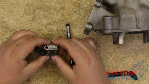
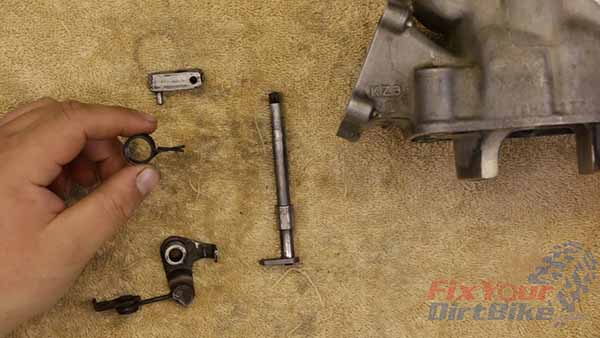
Start by assembling the linkage.

  1. Insert the bushing into the valve link, small side down.
  2. Install the spring with the spring ends facing up.
  3. Compress the spring and rest it in the stop.
  4. Place the drive pinion on top of the linkage with the pin between the spring ends.
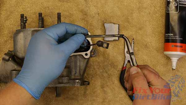
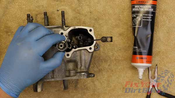
  5. Apply grease to the driveshaft bushing and driveshaft. Fit the bushing on the driveshaft and Install the drive shaft partway into the cylinder.
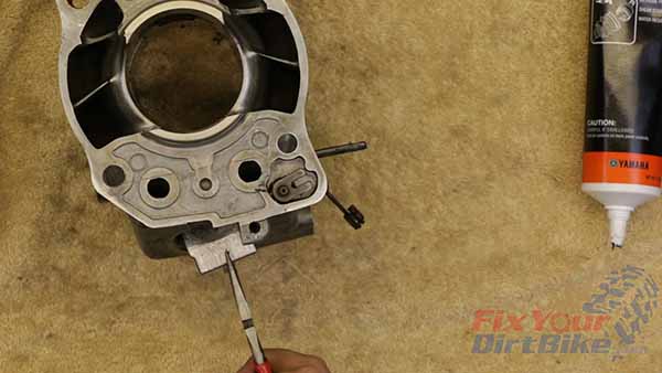
  6. Align the link assembly and finish installing the driveshaft.
  7. Clip the driveshaft into the linkage.
1997 - 2001 Honda CR250 - Top End Service - Part 10 - Exhaust Valve Installation - Assemble Linkage

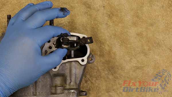
Place the drive pinion on top of the linkage with the pin between the spring ends.
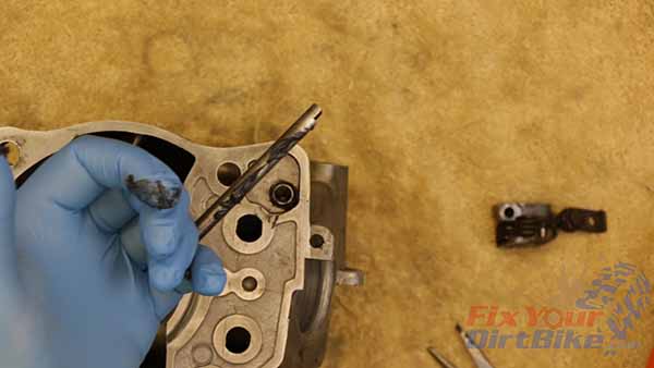
Apply grease to the driveshaft bushing and driveshaft. Fit the bushing on the driveshaft, and Install drive shaft part way into the cylinder.
Apply grease to the driveshaft bushing and driveshaft. Fit the bushing on the driveshaft and Install the drive shaft partway into the cylinder.

1997 - 2001 Honda CR250 - Top End Service - Part 10 - Exhaust Valve Installation - Grease Drive Shaft Bushing

Align the link assembly, and finish installing the driveshaft.
Align the link assembly and finish installing the driveshaft.
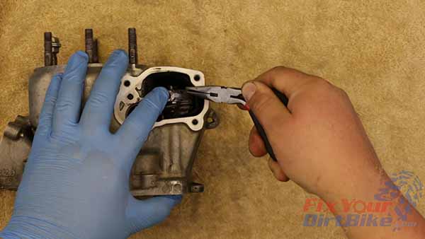
Clip the driveshaft into the linkage.
Exhaust Valve Governor Install

  1. Apply grease to the pinion shaft and bushing—seat bushing in the crankcase.
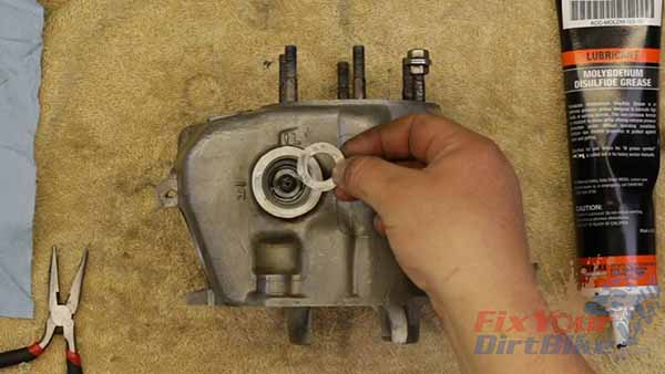
  2. Assemble the governor washers and engage the rack. Install the governor in the crankcase.
  3. Install a pinion shaft with the opening facing in. Double-check the rack and pinion operation.
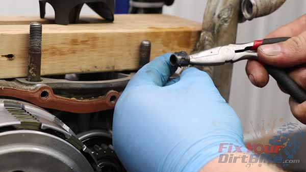
 Apply grease to the pinion shaft and bushing. Seat bushing in the crankcase.
Apply grease to the pinion shaft and bushing—seat bushing in the crankcase.
Assemble the governor washers and engage the rack. Install the governor in the crankcase
Assemble the governor washers and engage the rack. Install the governor in the crankcase.e
Install pinion shaft with the opening facing in. Double-check the rack and pinion operation.
Flap Valve Assembly

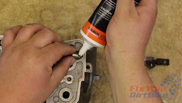
  1. Apply grease to the flap valve shaft and partially install it into the cylinder.
  2. Install the flap valve with the projections facing up. Align and install the flap valve.
  • 97-98 – Through the exhaust port.
  • 99-01 – Through the cylinder
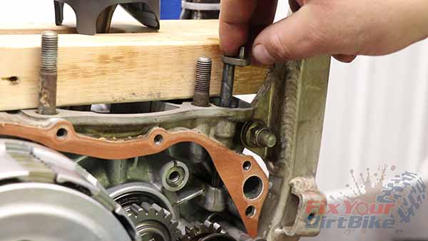
 Apply grease to the flap valve shaft, and partially install it into the cylinder.
Apply grease to the flap valve shaft and partially install it into the cylinder.
Install the flap valve with the projections facing up. Align and install the flap valve.

Related: I don’t trust oil injection systems, and here’s why!

Right Sub-Exhaust Valve Install

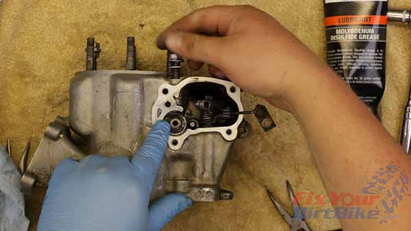
  1. Apply grease to the exhaust valve shaft and connect it to the valve.
  2. Align the valve shaft with the flap valve and place the sub-exhaust valve on its bore. Apply 2-stroke Oil to the valve, then press it into the cylinder.
  3. Turn the valve until the cutout is facing up, and install the stopper bolt hand tight.
  4. Install bearings with the manufacturer’s marks facing out.
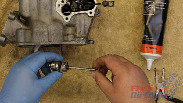
Apply grease to the exhaust valve shaft, and connect it to the valve.
Apply grease to the exhaust valve shaft and connect it to the valve.
Align the valve shaft with the flap valve, and place the sub-exhaust valve on it’s bore. Apply 2-stroke oil to the valve, then press the valve into the cylinder.
Align the valve shaft with the flap valve and place the sub-exhaust valve on its bore. Apply 2-stroke Oil to the valve, then press it into the cylinder.
Turn the valve until the cutout is facing up, and install the stopper bolt hand tight.
Install bearings with the manufacturer’s marks facing out.
Connect Valve Linkage

  • Seat the valve link against the end of the valve so the tab sits in the cutout. Rotate the valve counter-clockwise and insert a drift into the hole.
  • Install the hex bolt and torque to 48 in-lb.
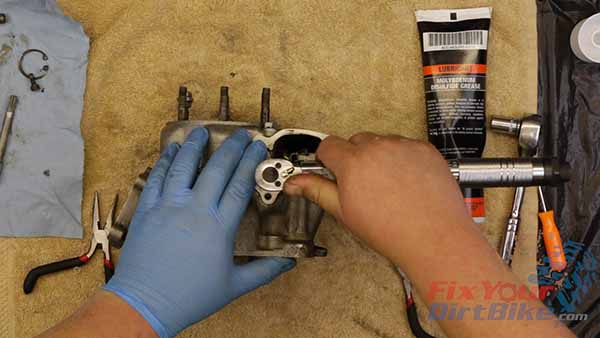
Top End Service - Part 10 - Exhaust Valve Installation - Tighten Valve Linkage

Install the hex bolt and torque to 48 in-lb.

Left Sub-Exhaust Valve Install

Lubricate the left Sub-Exhaust valve with 2-stroke Oil. Align the valve with the valve shaft and press it into the bore.

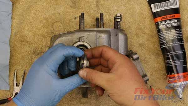
Lubricate and install the bearings with the markings facing out.

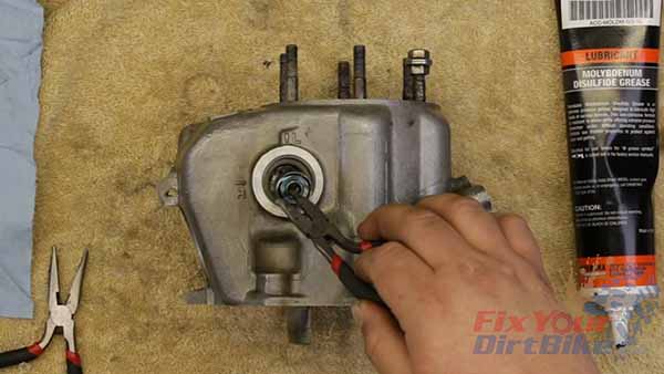
Install the collar with the stepped side facing in, followed by the snap ring.

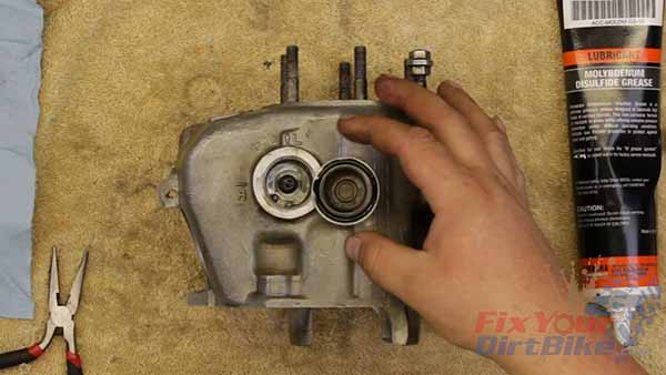
Lubricate a new o-ring and install it on the valve cap.

Apply grease to the valve cap threads, and install the cap hand-tight.
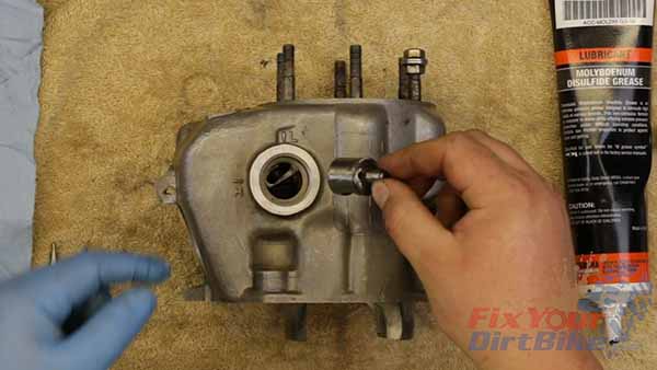
 Lubricate the left Sub-Exhaust valve with 2-stroke oil. Align the valve with the valve shaft, and press it into the bore.
Lubricate the left Sub-Exhaust valve with 2-stroke Oil. Align the valve with the valve shaft and press it into the bore.
Lubricate and install the bearings with the markings facing out.
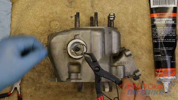
Install the collar with the stepped side facing in, followed by the snap ring.

1997 - 2001 Honda CR250 - Top End Service - Part 10 - Left Side Snap Ring

Lubricate a new o-ring, and install it on the valve cap.
Lubricate a new o-ring and install it on the valve cap.
Apply grease to the valve cap threads, and install the cap hand tight.
Apply grease to the valve cap threads, and install the cap hand-tight.
Test Power Valve Operation

  1. Tighten the hex bolt on the pinion holder temporarily and test the operation of the exhaust valve system.
  2. Loosen the pinion bolt; you must adjust the system after installing the cylinder.
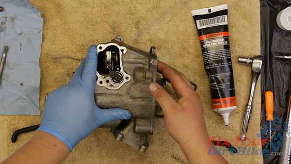
 Tighten the hex bolt on the pinion holder temporarily, and test the operation of the exhaust valve system.
Tighten the hex bolt on the pinion holder temporarily and test the operation of the exhaust valve system.

Exhaust Valve Torque Specifications

  • Linkage Hex Bolt – 48 in-lb.
  • Pinion Hex Bolt – 48 in-lb.

← Part 9: Clearance Calculations

Part 11: Piston Installation →

Keep Your ’97-’01 CR250 Running Right!
This site uses Akismet to reduce spam. Learn how your comment data is processed.